| Parameter |
Description |
Note |
| Supported GNSS constellations |
Option 1:
GPS L1(C/A),L5; NavIC L5,S;
Galileo E1; SBAS L1
Option 2:
GPS L1(C/A), L2(CM), L5;
GLONASS L1(C/A), L2(C/A);
Galileo E1B, E1C, E5b; NavIC L5
Option 3:
GPS L1(C/A),L2(CM); Beidou B1; Galileo E1;SBAS L1
Option 4:
GPS L1, L2 (C/A, M-code);
Galileo E1 |
Simultaneous GNSS signal reception
Option 1 by default.
All other constellations available by request
C/A, CM codes: PVT digital out and interference-clear RF out
M-code: – RF output only, hardware ready (not tested).
|
| Interference rejection: |
| Single jammer interference resistance |
Up to 40* dB |
Single jammer:
– one CW signal centered at the 1575,42 МНz;
– one CW signal centered at the 1227,6 МНz; |
| Up to 30* dB |
Single jammer:
– one AWGN signal centered at the 1575,42 МНz and 40 MHz bandwidth;
– one AWGN signal centered at the 1227,6 МНz and 30 MHz bandwidth; |
| Several interference suppression (up to three) |
Up to 32* dB |
Each of jammer:
– one CW signal centered at the 1575,42 МНz;
– one CW signal centered at the 1227,6 МНz; |
| Up to 23* dB |
Each of jammer:
– one AWGN signal centered at the 1575,42 МНz and 40 MHz bandwidth;
– one AWGN signal centered at the 1227,6 МНz and 30 MHz bandwidth; |
| Interference resistance: |
| Single jammer interference resistance |
Up to 90 dB (J/S) |
|
| Several jammers interference resistance (up to three) |
Up to 82 dB (J/S) |
|
| Number of receiver channels |
4 for each frequency band |
|
| Positioning accuracy (RMS): |
| -horizontal |
2.1 m |
|
| -vertical |
3.8 m |
|
| Data interfaces |
3xRS422 |
|
| Peripheral interfaces |
1x1PPS out |
|
| Up-converter RF output (optional*) |
1 pcs |
Clear GNSS signal. L1 band by default. Other bands by request. |
| GNSS+INS coupling (optional available by request*) |
with onboard MEMS sensor |
With external IMU via RS422 (optional available by request*) |
| Data protocols |
NMEA, NTL Binary |
|
| Data update rate: |
|
|
| Standalone mode |
20 Hz |
PVT data |
| Raw ranging measurements |
20 Hz |
|
| GNSS+INS mode |
200 Hz |
PVT data |
| Operation conditions: |
| Altitude |
18000 m |
up to 50000 m by request |
| Velocity |
512 m/s |
up to 3000 m/s by request |
| Supply voltage |
12V…36V, 24V typical |
|
| Power consumption |
<15.0W (typical) |
max <19W (with three bands up-converter) |
| Dimensions |
210.5 mm х 160 mm x 52 mm |
|
| Weight |
<2000 g |
|
| Operating temperature |
– 40°C …+ 71°C |
|
| Storage temperature |
– 45°C … + 85°C |
|
| Environmental |
According to MIL-STD 810G |
514.6, 501.5, 502.5, 500.5, 516.6, 510.5, 503.5, 516.6, 513.6, 507.5, 509.5, 504.1 |
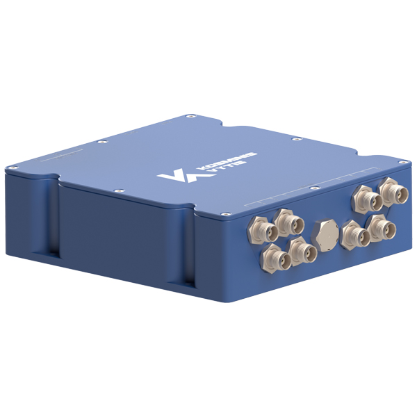
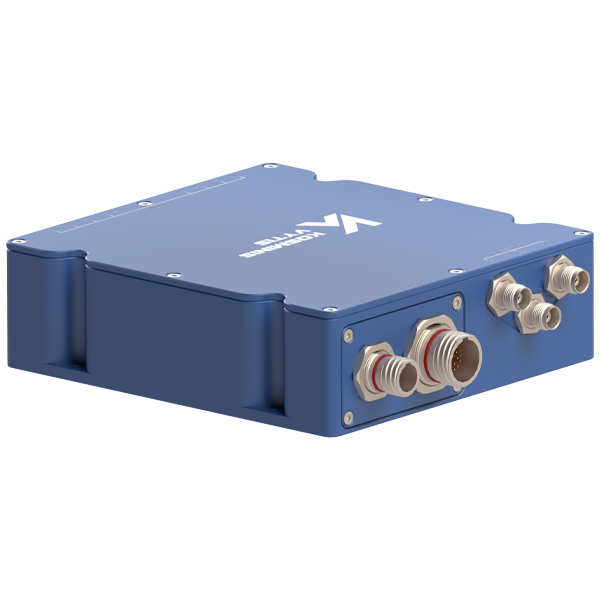
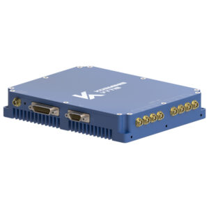
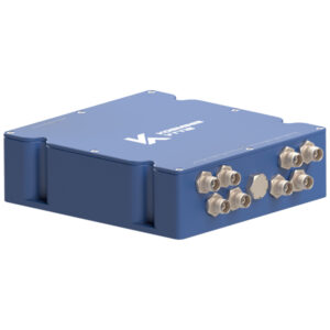
| Connectors |
4xSMA Female (L1, E1)
4xSMA Female (L2)
|
RF IN+DC Antenna Out |
| 1xSMA Female (L1, E1, L2) |
RF OUT |
| D38999/21NA98PN (Amphenol Aerospace)
Circular MIL Spec Connector HERMETIC |
Power |
| D38999/21YC35PN (Amphenol Aerospace)
Circular MIL Spec Connector HERMETIC |
Data |
| EMC / EMI |
According to MIL-STD 461G |
CE101, CE102, CE106, CS101, CS106, CS114, CS115, CS116, RE101, RE102, RS101, RS103 |


